When a customer reports poor control, unstable ventilation, strange readings, or alarms, the first reaction is often to assume the sensor has failed.
But in practice, sensor faults are only one part of the problem.
Before replacing a CDT sensor (Carbon Dioxide Transmitter / environmental transmitter), work through a structured field diagnosis process. Most faults can be narrowed down in minutes without opening the indoor unit or replacing parts.
Step 1 – Check What the Controller Sees
Before touching wiring, log into the controller or BMS and review the live value.
Questions to ask:
✓ Is the value changing?
✓ Is the value realistic?
✓ Has the value flatlined?
Typical CO₂ ranges: If a sensor or controller has a display first check;
| Reading | Typical Interpretation |
|---|---|
| 0 ppm | Sensor power or wiring fault |
| 400–600 ppm | Normal fresh indoor air |
| 800–1200 ppm | Occupied space |
| 1500–2000 ppm | High occupancy or ventilation issue |
| Constant value | Sensor, scaling or communications issue |
Quick field check:
Breath on or place 2–3 people near the sensor for several minutes.
A functioning CO₂ sensor should begin increasing.
If nothing changes, continue testing.
Step 2 – Verify Sensor Power
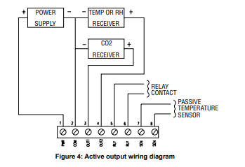
Measure directly at the sensor terminals.
Common supply voltages: CDT can be either 24VAC or 24VDC RATED: Power Requirements: 16-35 VDC or 19-28 VAC.
Expected:
- Stable supply
- No excessive voltage drop
- No intermittent cycling
Symptoms of power problems:
- Reading jumps
- Random alarms
- Sensor never stabilises
- Output fixed at zero
Step 3 – Identify the Sensor Output Type
This changes the entire diagnostic method.
Analogue Outputs
0–10V
Measure DC voltage.
Typical example:
0–10V = 0–2000 ppm
Expected:
- 400 ppm ≈ 2V
- 1000 ppm ≈ 5V
- 2000 ppm ≈ 10V
4–20mA
Measure loop current.
Typical operating values:
- 4mA = minimum
- 20mA = maximum
- 6–10mA = common occupied conditions
Digital Outputs
- Modbus
- BACnet
- KNX
For digital sensors:
- Check device online status
- Confirm address
- Verify register mapping
- Compare raw values to engineering values
Step 4 – Perform a Response Test
A sensor that does not move is usually more suspicious than one showing a high value.
Breath Test (Room Sensors)
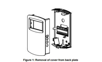
Remove cover if required.
Gently breathe near the sensing area for 10–20 seconds.
Expected:
- Reading should rise within approximately 30–90 seconds.
No response:
- Sensor fault
- Dead sensing element
- Communication issue
Fresh Air Test
Expose sensor to fresh outside air.
Expected:
- Reading should decrease.
No movement:
- Continue investigation.
Step 5 – Compare With a Reference Instrument
Best practice is to carry a portable meter.
Examples: Testo, TSI ,Vaisala
Compare: Portable meter vs Installed sensor
Acceptable tolerance depends on application, but large deviations usually indicate calibration or installation issues.
Step 6 – Test the Controller (Fast Isolation Method)
If accessible: Disconnect the sensor output. Inject a known signal.
Example: Inject 5VDC into a 0–10V analogue input.
Expected: Controller should display approximately mid-scale.
If controller responds correctly: → Sensor problem
If controller does not respond: → Input configuration or hardware issue
Common Faults Found in the Field
| Symptom | Most Likely Cause |
|---|---|
| Fixed value | Sensor failed |
| Zero reading | No power |
| Reading unstable | Wiring/noise |
| High reading only | Poor ventilation |
| Controller wrong but sensor correct | Scaling issue |
| Sensor offline | Communications fault |
Final Tip for Service Technicians
Don’t replace the sensor first.
Work in this order:
Controller → Power → Signal → Response → Reference Meter → Replacement
A 5-minute diagnosis can save a return visit and unnecessary replacement parts.
Full Diagnostic Procedure – Installation instructions
Final Rule for Service Techs
Don’t calibrate first.
Work in this order:
Power → Output → Scaling → Location → Response → Calibration
Nine times out of ten, the sensor is telling the truth and the system around it is not.
Controls Direct – Independent HVAC controls knowledge for technicians in the field.